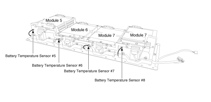
Kia Soul EV: High Voltage Battery Control System / Battery Temperature Sensor Repair procedures
Kia Soul EV (PS EV) 2015-2020 Service Manual / EV Battery System / High Voltage Battery Control System / Battery Temperature Sensor Repair procedures
| Installation |
Battery temperature sensor can not be disassembled. |
| 1. |
Turn the ignition switch OFF. |
| 2. |
Shut off the high voltage.
(Refer to Battery Control System - "High Voltage Shut-off Procedure") |
| 3. |
Remove the high voltage battery system assembly.
(Refer to High Voltage Battery System - Repair procedures - "Removal") |
| 4. |
Remove the high voltage battery pack upper case.
(Refer to High Voltage Battery System - Case - "Upper Case") |
| 5. |
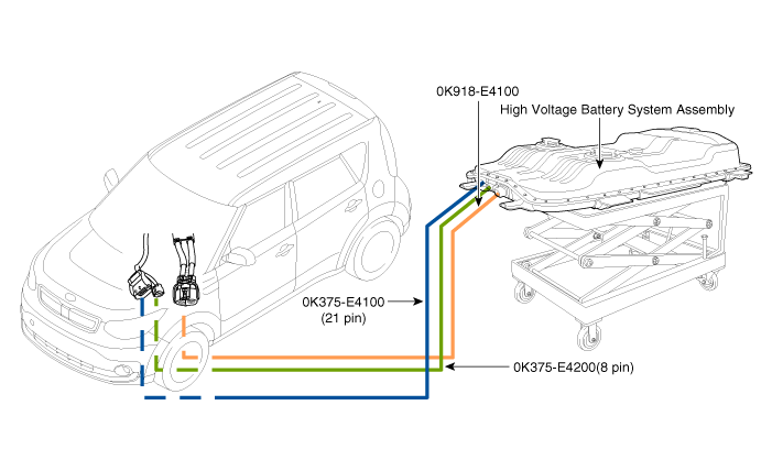
Connect the SST (No: 0K918-E4100, 0K375-E4100, 0K375-E4200) as shown in the image below.
|
| 6. |
Connect the GDS to DLC. |
| 7. |
Turn the ignition switch ON. |
| 8. |
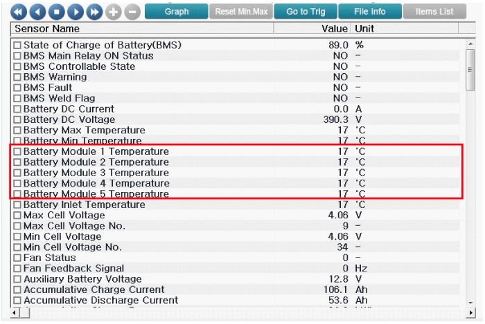
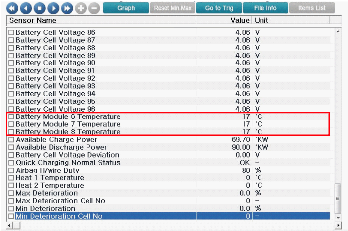
Check the "Battery Module Temperature" in the GDS service data.
|
| 9. |
Turn the ignition swtich OFF. |
| 10. |
Disconnect the SST (high votlage battery cable & BMS terminal). |
| 11. |
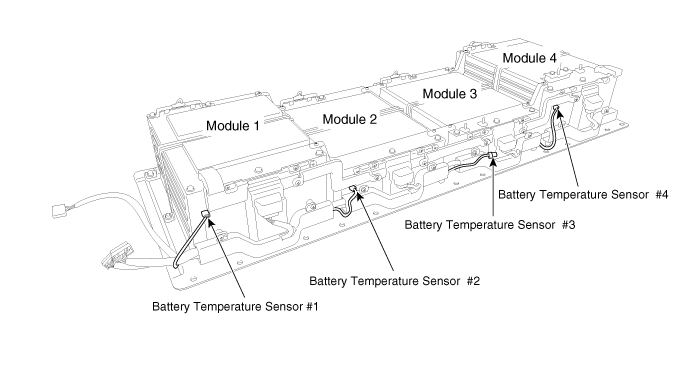
Check resistance for each temperature sensor.
|
 Battery Temperature Sensor Schematic Diagrams
Circuit Diagram
...
 Runaway Arresting Device (RAD) Specifications
Specification
ItemSpecificationRemarkRAD Combined Resistance (?)Less than 3 (20°C)Checkable by multi testerRAD Terminal Resistance (?)Less than 0.375 (20°C)Checkable by multi testerRAD Switch P ...
Other information:
Kia Soul EV (PS EV) 2015-2020 Service Manual: Battery Temperature Sensor Description and Operation
Description Installed in the high voltage battery module, Battery Temperature Sensor transfers temperature of each battery module to BMS ECU. ...
Kia Soul EV (PS EV) 2015-2020 Service Manual: Components and Components Location
Components 1. Main crash pad assembly2. Crash pad side cover [LH]3. Crash pad side cover [RH]4. Crash pad lower panel5. Knee bolster panel6. Steering column shroud lower panel7. Center support floor mounting bracket ...
Copyright © www.ksoulev.com 2020-2025


