Kia Soul EV: High Voltage Battery Control System / Battery Management System (BMS) ECU Schematic Diagrams
Kia Soul EV (PS EV) 2015-2020 Service Manual / EV Battery System / High Voltage Battery Control System / Battery Management System (BMS) ECU Schematic Diagrams
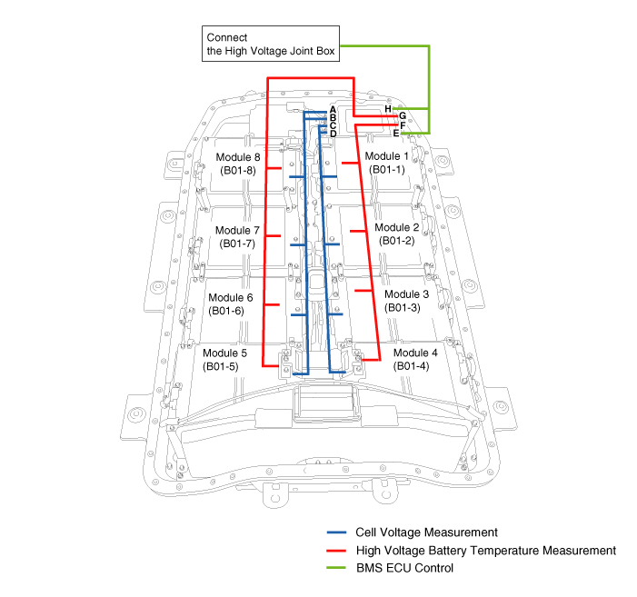
| System Circuit Diagram |
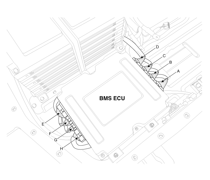
| Connector Location |
| BMS ECU Connector And Terminal Function |
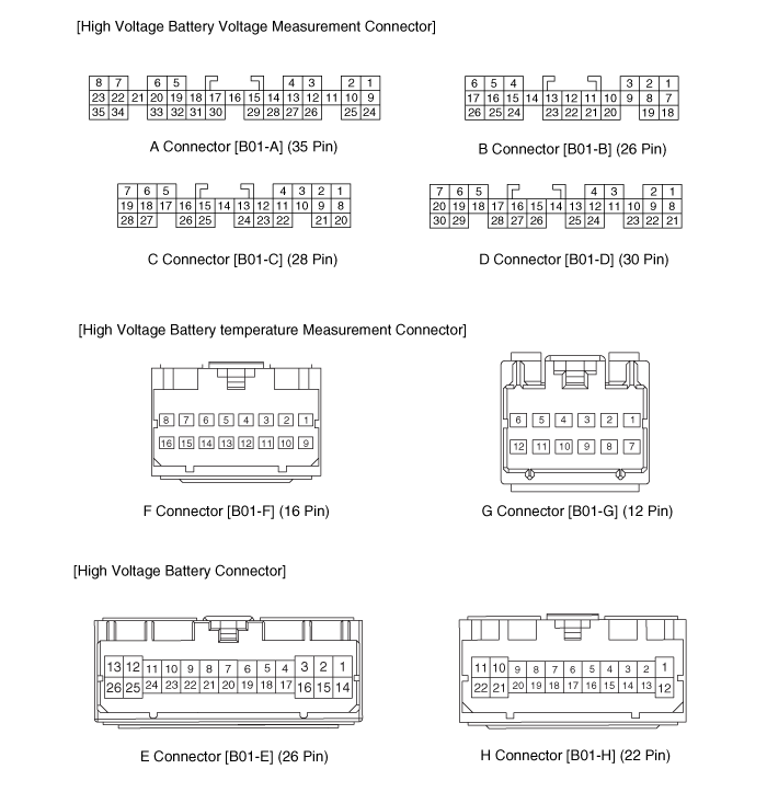
| BMS ECU Terminal Function |
A Connector [B01-A] (35 Pin) - Voltage Measurement Connector
| Pin no. | Description | Connected to |
| 1 | Battery Cell [Module 8/Cell 13] Voltage Input | Battery Cell [Module 8/Cell 13] |
| 2 | Battery Cell [Module 8/Cell 10] Voltage Input | Battery Cell [Module 8/Cell 10] |
| 3 | Battery Cell [Module 8/Cell 7] Voltage Input | Battery Cell [Module 8/Cell 7] |
| 4 | Battery Cell [Module 8/Cell 4] Voltage Input | Battery Cell [Module 8/Cell 4] |
| 5 | Battery Cell [Module 7/Cell 4] Voltage Input | Battery Cell [Module 7/Cell 4] |
| 6 | Battery Cell [Module 7/Cell 1] Voltage Input | Battery Cell [Module 7/ Cell 1] |
| 7 | Battery Cell [Module 6/Cell 8] Voltage Input | Battery Cell [Module 6/Cell 8] |
| 8 | Battery Cell [Module 6/Cell 5] Voltage Input | Battery Cell [Module 6/ Cell 5] |
| 9 | Battery Cell [Module 8/Cell 14] Voltage Input | Battery Cell [Module 8/Cell 14] |
| 10 | Battery Cell [Module 8/Cell 11] Voltage Input | Battery Cell [Module 8/Cell 11] |
| 11 | Battery Cell [Module 8/Cell 9] Voltage Input | Battery Cell [Module 8/Cell 9] |
| 12 | Battery Cell [Module 8/Cell 7] Voltage Input | Battery Cell [Module 8/Cell 7] |
| 13 | Battery Cell [Module 8/Cell 5] Voltage Input | Battery Cell [Module 8/Cell 5] |
| 14 | Battery Cell [Module 8/Cell 2] Voltage Input | Battery Cell [Module 8/Cell 2] |
| 15 | Battery Cell [Module 8/the Lower Line Cell] Voltage Input | Battery Cell [Module 8] |
| 16 | Battery Cell [Module 7/Cell 10] Voltage Input | Battery Cell [Module 7/Cell 10] |
| 17 | Battery Cell [Module 7/Cell 8] Voltage Input | Battery Cell [Module 7/Cell 8] |
| 18 | Battery Cell [Module 7/Cell 6] Voltage Input | Battery Cell [Module 7/Cell 6] |
| 19 | Battery Cell [Module 7/Cell 5] Voltage Input | Battery Cell [Module 7/Cell5] |
| 20 | Battery Cell [Module 7/Cell 2] Voltage Input | Battery Cell [Module 7/Cell 2] |
| 21 | Battery Cell [Module 7/the Lower Line Cell] Voltage Input | Battery Cell [Module 7] |
| 22 | Battery Cell [Module 6/Cell 9] Voltage Input | Battery Cell [Module 6/Cell 9] |
| 23 | Battery Cell [Module 6/Cell 6] Voltage Input | Battery Cell [Module 6/Cell 6] |
| 24 | - | |
| 25 | Battery Cell [Module 8/Cell 12] Voltage Input | Battery Cell [Module 8/Cell 12] |
| 26 | Battery Cell [Module 8/Cell 8] Voltage Input | Battery Cell [Module 8/Cell 8] |
| 27 | Battery Cell [Module 8/Cell 6] Voltage Input | Battery Cell [Module 8/Cell6] |
| 28 | Battery Cell [Module 8/Cell 3] Voltage Input | Battery Cell [Module 8/Cell 3] |
| 29 | Battery Cell [Module 8/Cell 1] Voltage Input | Battery Cell [Module 8/Cell1] |
| 30 | Battery Cell [Module 7/Cell 9] Voltage Input | Battery Cell [Module 7/Cell 9] |
| 31 | Battery Cell [Module 7/Cell 7] Voltage Input | Battery Cell [Module 7/Cell 7] |
| 32 | Battery Cell [Module 7/Cell 5] Voltage Input | Battery Cell [Module 7] |
| 33 | Battery Cell [Module 7/Cell 3] Voltage Input | Battery Cell [Module 7/Cell 3] |
| 34 | Battery Cell [Module 6/Cell 10] Voltage Input | Battery Cell [Module 6/Cell 10] |
| 35 | Battery Cell [Module 6/Cell 7] Voltage Input | Battery Cell [Module 6/Cell 7] |
B Connector [B01-B] (26 Pin) - Voltage Measurement Connector
| Pin no. | Description | Connected to |
| 1 | Battery Cell [Module 6/Cell 3] Voltage Input | Battery Cell [Module 6/Cell 3] |
| 2 | Battery Cell [Module 6/Cell the Lower Line] Voltage Input | Battery Cell [Module 6] |
| 3 | - | ? |
| 4 | Battery Cell [Module 5/Cell 6] Voltage Input | Battery Cell [Module 5/Cell 6] |
| 5 | Battery Cell [Module 5/Cell 3] Voltage Input | Battery Cell [Module 5/Cell 3] |
| 6 | Battery Cell [Module 5/Cell the Lower Line] Voltage Input | Battery Cell [Module 5] |
| 7 | Battery Cell [Module 6/Cell 4] Voltage Input | Battery Cell [Module 6/Cell 4] |
| 8 | Battery Cell [Module 6/Cell 1] Voltage Input | Battery Cell [Module 6/Cell 1] |
| 9 | - | ? |
| 10 | Battery Cell [Module 5/Cell 13] Voltage Input | Battery Cell [Module 5/Cell 13] |
| 11 | Battery Cell [Module 5/Cell 11] Voltage Input | Battery Cell [Module 5/Cell 11] |
| 12 | Battery Cell [Module 5/Cell 9] Voltage Input | Battery Cell [Module 5/Cell 9] |
| 13 | Battery Cell [Module 5/Cell 7] Voltage Input | Battery Cell [Module 5/ Cell 7] |
| 14 | - | ? |
| 15 | Battery Cell [Module 5/Cell 7] Voltage Input | Battery Cell [Module 5/Cell 7] |
| 16 | Battery Cell [Module 5/Cell 4] Voltage Input | Battery Cell [Module 5/Cell 4] |
| 17 | Battery Cell [Module 5/Cell 1] Voltage Input | Battery Cell [Module 5/Cell 1] |
| 18 | Battery Cell [Module 6/Cell 5] Voltage Input | Battery Cell [Module 6/Cell 5] |
| 19 | Battery Cell [Module 6/Cell 2] Voltage Input | Battery Cell [Module 6/Cell 2] |
| 20 | Battery Cell [Module 5/Cell 14] Voltage Input | Battery Cell [Module 5/Cell 14] |
| 21 | Battery Cell [Module 5/Cell 12] Voltage Input | Battery Cell [Module 5/Cell 12] |
| 22 | Battery Cell [Module 5/Cell 10] Voltage Input | Battery Cell [Module 5/Cell 10] |
| 23 | Battery Cell [Module 10/Cell 1] Voltage Input | Battery Cell [Module 10/Cell 1] |
| 24 | - | ? |
| 25 | Battery Cell [Module 5/Cell 5] Voltage Input | Battery Cell [Module 5/Cell 5] |
| 26 | Battery Cell [Module 5/Cell 2] Voltage Input | Battery Cell [Module 5/Cell 2] |
C Connector [B01-C] (28 Pin) - Voltage Measurement Connector
| Pin no. | Description | Connected to |
| 1 | Battery Cell [Module 4/Cell 12] Voltage Input | Battery Cell [Module 4/Cell 12] |
| 2 | Battery Cell [Module 4/Cell 9] Voltage Input | Battery Cell [Module 4/Cell 9] |
| 3 | Battery Cell [Module 4/Cell 7] Voltage Input | Battery Cell [Module 4/Cell 7] |
| 4 | Battery Cell [Module 4/Cell 5] Voltage Input | Battery Cell [Module 4/Cell 5] |
| 5 | Battery Cell [Module 3/Cell 5] Voltage Input | Battery Cell [Module 3/Cell 5] |
| 6 | Battery Cell [Module 3/Cell 3] Voltage Input | Battery Cell [Module 3/Cell 3] |
| 7 | Battery Cell [Module 3/Cell the Lower Line] Voltage Input | Battery Cell [Module 3] |
| 8 | Battery Cell [Module 4/Cell 13] Voltage Input | Battery Cell [Module 4/Cell 13] |
| 9 | Battery Cell [Module 4/Cell 10] Voltage Input | Battery Cell [Module 4/Cell 10] |
| 10 | Battery Cell [Module 4/Cell 8] Voltage Input | Battery Cell [Module 4/Cell 8] |
| 11 | Battery Cell [Module 4/Cell 6] Voltage Input | Battery Cell [Module 4/Cell 6] |
| 12 | Battery Cell [Module 4/Cell 3] Voltage Input | Battery Cell [Module 4/Cell 3] |
| 13 | Battery Cell [Module 4/Cell 1] Voltage Input | Battery Cell [Module 4/Cell 1] |
| 14 | Battery Cell [Module 4/ the Lower Line Cell] Voltage Input | Battery Cell [Module 4] |
| 15 | Battery Cell [Module 3/Cell 9] Voltage Input | Battery Cell [Module 3/Cell 9] |
| 16 | Battery Cell [Module 3/Cell 7] Voltage Input | Battery Cell [Module 3/Cell 7] |
| 17 | Battery Cell [Module 3/Cell 6] Voltage Input | Battery Cell [Module 3/Cell 6] |
| 18 | Battery Cell [Module 3/Cell 4] Voltage Input | Battery Cell [Module 3/Cell4] |
| 19 | Battery Cell [Module 3/Cell 1] Voltage Input | Battery Cell [Module 3/Cell1] |
| 20 | Battery Cell [Module 4/Cell 14] Voltage Input | Battery Cell [Module 4/Cell 14] |
| 21 | Battery Cell [Module 4/Cell 11] Voltage Input | Battery Cell [Module 4/Cell 11] |
| 22 | Battery Cell [Module 4/Cell 7] Voltage Input | Battery Cell [Module 4/Cell 7] |
| 23 | Battery Cell [Module 4/Cell 4] Voltage Input | Battery Cell [Module 4/Cell 4] |
| 24 | Battery Cell [Module 4/Cell 2] Voltage Input | Battery Cell [Module 4/Cell 2] |
| 25 | Battery Cell [Module 3/Cell 10] Voltage Input | Battery Cell [Module 3/Cell 10] |
| 26 | Battery Cell [Module 3/Cell 8] Voltage Input | Battery Cell [Module 3/Cell 8] |
| 27 | Battery Cell [Module 3/Cell 5] Voltage Input | Battery Cell [Module 3/Cell 5] |
| 28 | Battery Cell [Module 3/Cell 2] Voltage Input | Battery Cell [Module 3/Cell 2] |
D Connector [B01-D] (30 Pin) - Voltage Measurement Connector
| Pin no. | Description | Connected to |
| 1 | Battery Cell [Module 2/Cell 8] Voltage Input | Battery Cell [Module 2/Cell 8] |
| 2 | Battery Cell [Module 2/Cell 5] Voltage Input | Battery Cell [Module 2/Cell 5] |
| 3 | Battery Cell [Module 2/Cell 3] Voltage Input | Battery Cell [Module 2/Cell 3] |
| 4 | Battery Cell [Module 2/ the Lower Line Cell] Voltage Input | Battery Cell [Module 2] |
| 5 | Battery Cell [Module 1/Cell 5] Voltage Input | Battery Cell [Module 1/Cell 5] |
| 6 | Battery Cell [Module 1/Cell 2] Voltage Input | Battery Cell [Module 1/Cell 2] |
| 7 | - | |
| 8 | Battery Cell [Module 2/Cell 9] Voltage Input | Battery Cell [Module 2/Cell 9] |
| 9 | Battery C |
 Battery Management System (BMS) ECU Specifications
Specification
ItemSpecificationRemarkC-CAN terminating resistance (?)Approx. 60Combined resistance (BMS ECU-Inverter)C-CAN terminating resistnace (?)Approx. 120BMS ECU resistance
...
 Battery Management System (BMS) ECU Repair procedures
Inspection
C-CAN Terminating Resistance Inspection (Multi Purpose Check Connector)
1.
Turn the ignition OFF.
2.
Measure the resistance between pins No. 20 and No. 17 of multi purpose check ...
Other information:
Kia Soul EV (PS EV) 2015-2020 Service Manual: Front Driveshaft Repair procedures
Replacement 1. Loosen the wheel nuts slightly. Raise the vehicle, and make sure it is securely supported. 2. Remove the front wheel and tire (A) from front hub. Tightening torque: 88.3 ~ 107.9 N.m (9.0 ~ 11.0 kgf.m, 65.1 ~ 79.6 lb-ft) Be careful not to da ...
Kia Soul EV (PS EV) 2015-2020 Service Manual: Rear Disc Brake Components and Components Location
Components 1. Guide rod bolt2. Bleed screw3. Caliper carrier4. Caliper body5. Brake pad6. Pad retainer ...
Copyright © www.ksoulev.com 2020-2025
