Kia Soul EV: Interior Trim / Luggage Side Trim Repair procedures
Kia Soul EV (PS EV) 2015-2020 Service Manual / Body (Interior and Exterior) / Interior Trim / Luggage Side Trim Repair procedures
| Replacement |
|

|

| 1. |
Remove the rear seat cushion assembly.
(Refer to Rear Seat - "Rear Seat Assembly") |
| 2. |
Remove the rear seat back assembly.
(Refer to Rear Seat - "Rear Seat Assembly") |
| 3. |
Remove the rear door scuff trim.
(Refer to Interior Trim - "Door Scuff Trim") |
| 4. |
Remove the rear transverse trim.
(Refer to Interior Trim - "Rear Transverse Trim") |
| 5. |
After loosening the mounting bolts, remove the rear seat lower side bracket (A) [LH,RH].
|
| 6. |
Carefully remove the rear door body side weatherstrip. |
| 7. |
Carefully remove the tail gate weatherstrip. |
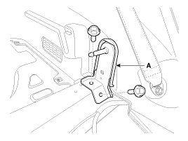
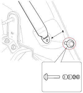
| 8. |
After loosening the mounting bolt, remove the rear seat belt lower anchir (A).
|
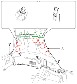
| 9. |
After loosening the mounting screw, remove the luggage side trim (A).
|
| 10. |
Install in the reverse order of removal.
|

 Luggage Side Trim Components and Components Location
Component Location
1. Luggage side trim
...
 Rear Pillar Trim Components and Components Location
Component Location
1. Rear pillar trim
...
Other information:
Kia Soul EV (PS EV) 2015-2020 Service Manual: Temperature Control Actuator Description and Operation
Description The heater unit includes mode control actuator and temperature control actuator. Located in the heater unit, the temperature control actuator regulates the temperature in the following procedures. Signal from control unit adjusts the position of the temperature door by operating ...
Kia Soul EV (PS EV) 2015-2020 Service Manual: Battery Temperature Sensor Description and Operation
Description Installed in the high voltage battery module, Battery Temperature Sensor transfers temperature of each battery module to BMS ECU. ...
Copyright © www.ksoulev.com 2020-2025
