Kia Soul EV: Indicators And Gauges / Instrument Cluster Repair procedures

Kia Soul EV (PS EV) 2015-2020 Service Manual / Body Electrical System / Indicators And Gauges / Instrument Cluster Repair procedures

Removal
1.
Disconnect the negative (-) battery terminal.
2.
Remove the cluster fascia panel.
(Refer to Body - "Cluster Fascia Panel")
3.
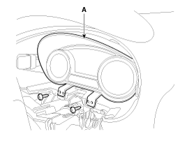
Remove the cluster (A) after removing screws.

4.
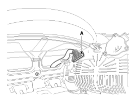
Disconnect the cluster connector (A) from the cluster.

Installation
1.
Connect the cluster connector.
2.
Install the cluster assembly.
3.
Install the cluster facia panel.
4.
Connect the negative (-) battery terminal.
   
After replacing the cluster with a new one, the "Variant Coding" procedure must be performed.
Inspection
1.
Check point (Warning indicator)
NO
Ref
Symbol
Color
Name
Signal Input
Signal Control
(Unit / Sensor)
Check Point
1

Green
Turn Left
C-CAN
GWAY
1)
CAN line failure
2

Green
Turn Right
C-CAN
3

Green
Front Fog
C-CAN
GWAY
1)
CAN line failure
4

Blue
High Beam
C-CAN
GWAY
1)
CAN line failure
5

Green
Low Beam
C-CAN
GWAY
1)
CAN Line failure
6

Green
Tail Lamp
C-CAN
GWAY
1)
CAN Line failure
7

Green
Cruise
C-CAN
VCU
1)
CAN line failure
8

Green
SET
C-CAN
GWAY
1)
CAN line failure
9

Red
Seat Belt
C-CAN
GWAY
1)
CAN line failure
10

Red
Air Bag
C-CAN
ACU
1)
CAN line failure
11

Yellow
Trunk Open
C-CAN
GWAY
1)
CAN line failure
12

Red
Door Open
C-CAN
BGWAY
1)
CAN line failure
13

Yellow
Immobilizer
C-CAN
GWAY
1)
CAN line failure
2)
Wiring failure
14

Yellow
ABS
C-CAN
ESC
1)
CAN line failure
15

Yellow
ESC
C-CAN
TCS
1)
CAN line failure
16

Yellow
ESC OFF
C-CAN
TCS
1)
CAN line failure
17

Yellow
TPMS
C-CAN
TPMS
1)
CAN line failure
18

Red
Parking Brake
C-CAN
GWAY
TCS
AHB
1)
CAN line failure
19

Red
Battery Charge
C-CAN
LDC
1)
Wiring failure
20

Yellow
Check Engine
C-CAN
EMS
1)
CAN line failure
21

Yellow
Low Washer
Hardwire
Water Level Sensor
1)
Wiring failure
22

Green
Active ECO
C-CAN
VCU
1)
CAN line failure
2)
Wiring failure
23

Red
MDPS
C-CAN
MDPS
1)
MDPS unit failure
2)
CAN line failure
24

Green
READY
C-CAN
VCU
1)
CAN line failure
25

Green
EV battery charge
Hardwire+C-CAN
BMS
1)
CAN line failure
2)
Wiring failure

Red
EMS
1)
CAN line failure
26

Yellow
EV System
C-CAN
VCU, MCU, BMS, LDC, FACT, OBC
1)
CAN line failure
27

Yellow
Power Down
C-CAN
VCU
1)
CAN line failure
28

Yellow
RBS
C-CAN
EBS

1)
CAN line failure
29

Yellow
Low Power
C-CAN
VCU
1)
CAN line failure
30

Yellow
EPB
C-CAN
EPB
1)
CAN line failure

2.
Check point (Gauge)
No.
Name
Signal Input
Signal Control
(Unit/Sensor)
Check Point
1
Speedometer
C-CAN
MCU
1)
CAN Line failure
2
SOC Gauge
C-CAN
BMS
1)
CAN Line failure
3
Power and Charge Gauge
C-CAN
VCU
1)
CAN Line failure

3.
Check the specified value of cluster connector in specified condition.
No.
Description
Input/Output
Communication
Value (V)
Specified Conditions
1
GND_Signal3
Input
Hardware
Above 5V
IGN switch ON , 
2
ILL(-)_OUT-
Output
Hardware
Below 1V
IGN switch ON, Tail switch ON, Rheostat Max
Instrument Cluster Description and Operation
Description Mian Features 1. Power and charge guage (1) It displays the degree of economic driving by identifying the status of a driver''s operation, depending on a vehicle''s driving cond ...

Troubleshooting
Troubleshooting Fault itemSymptomCheck pointRelated partsDisplayOLED-LCD NOT displaying  1) Check the connection between connectors 2) Check the Battery (+), Ignition and Ground wiring ...

Other information:

Kia Soul EV (PS EV) 2015-2020 Service Manual: Special Service Tools


Special Service Tools Tool Name / NumberIllustrationDescriptionRKE Battery Checker09954-2P100Used to measure the RKE battery voltage ...

Kia Soul EV (PS EV) 2015-2020 Service Manual: Electric A/C compressor Description and Operation


Description Electric compressors improve the fuel efficiency and operates the air conditioner even when the engine has stopped. Operation Principle Compression Part One of the scrolls is fixed while the other orbits eccentrically without self-rotating, thereby to trap and pump refrigeran ...

Copyright © www.ksoulev.com 2020-2024