Kia Soul EV: Indicators And Gauges / Instrument Cluster Components and Components Location
Kia Soul EV (PS EV) 2015-2020 Service Manual / Body Electrical System / Indicators And Gauges / Instrument Cluster Components and Components Location
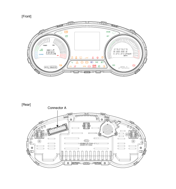
| Components |
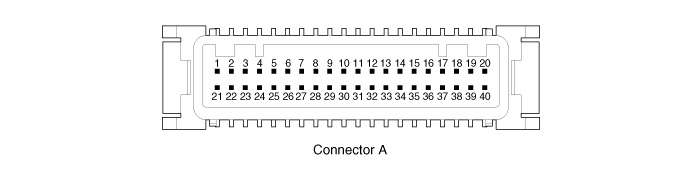
Connector Pin Information
| No. | Description | No. | Description |
| 1 | Ground signal 3 (Power ground) | 21 | Trip switch (-) input |
| 2 | Illumination output (-) | 22 | Trip switch 1 (+) input (Trip button) |
| 3 | Rheostat switch down input | 23 | Trip switch 2 (+) input (Cruise button) |
| 4 | Rheostat switch up input | 24 | - |
| 5 | Detent output (+) | 25 | - |
| 6 | P output (+) (A/T) | 26 | Low washer level input (-) |
| 7 | R output (+) (A/T) | 27 | - |
| 8 | N output (+) (A/T) | 28 | Heated wheel indicator input |
| 9 | D output (+) (A/T) | 29 | M CAN low |
| 10 | S output (+) (A/T) | 30 | M CAN high |
| 11 | ALT L output | 31 | - |
| 12 | - | 32 | C CAN high |
| 13 | - | 33 | C CAN low |
| 14 | - | 34 | - |
| 15 | Airbag (+) input | 35 | - |
| 16 | - | 36 | - |
| 17 | - | 37 | Ground signal 1 |
| 18 | Speed output (4P output) | 38 | - |
| 19 | IGN 3 | 39 | IGN 1 |
| 20 | Tail lamp input (Illumination (+)) | 40 | Battery (+) |
 Components and Components Location
Component Location
1. Cluster assembly2. Seat belt switch3. Brake fluid level warning switch4. Parking brake switch5. Door switch6. Tailgate switch7. Wheel speed sensor8. ABS ECU
...
 Instrument Cluster Schematic Diagrams
Circuit Diagram
...
Other information:
Kia Soul EV (PS EV) 2015-2020 Service Manual: Front Pillar Trim Components and Components Location
Component Location 1. Front pillar trim ...
Kia Soul EV (PS EV) 2015-2020 Service Manual: Center Fascia Panel Components and Components Location
Component Location 1. Center fascia panel ...
Copyright © www.ksoulev.com 2020-2025
