Kia Soul EV: Parking Brake System / Electric Parking Brake (EPB) Schematic Diagrams
Kia Soul EV (PS EV) 2015-2020 Service Manual / Brake System / Parking Brake System / Electric Parking Brake (EPB) Schematic Diagrams
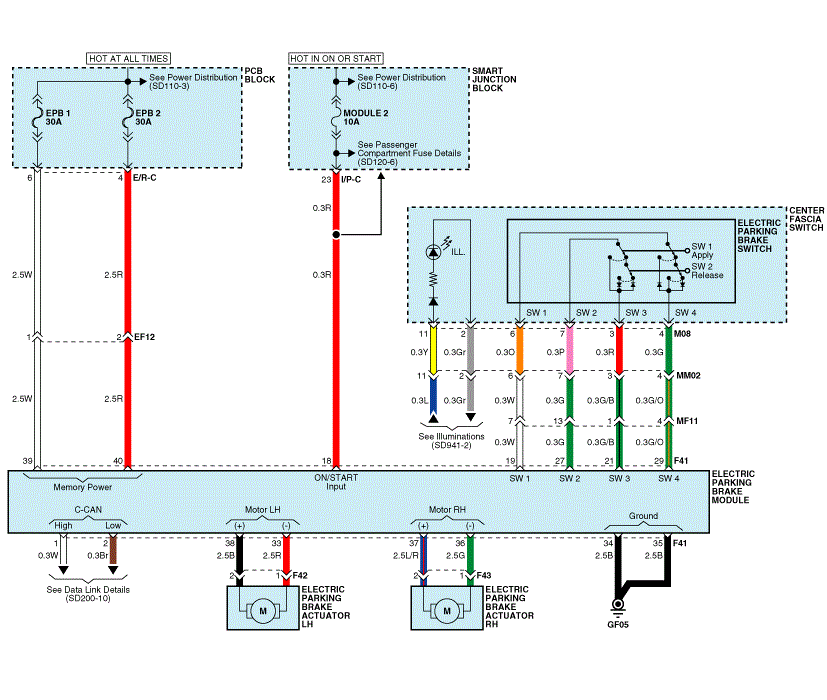
| EPB Circuit Diagram (1) |

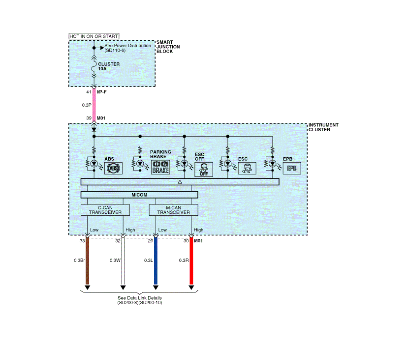
| EPB Circuit Diagram (2) |

| EPB connector input/output |

| Pin | Description | Pin | Description | ||
| 1 | W | C-CAN (High) | 21 | G/B | Center Fascia Switch (ElectronicParking Brake Switch (SW3)) |
| 2 | Br | C-CAN (Low) | 22 | - | - |
| 3 | - | - | 23 | - | - |
| 4 | - | - | 24 | - | - |
| 5 | - | - | 25 | - | - |
| 6 | - | - | 26 | - | - |
| 7 | - | - | 27 | G | Center Fascia Switch (ElectronicParking Brake Switch (SW2)) |
| 8 | - | - | 28 | - | - |
| 9 | - | - | 29 | G/O | Center Fascia Switch (ElectronicParking Brake Switch (SW4)) |
| 10 | - | - | 30 | - | - |
| 11 | - | - | 31 | - | - |
| 12 | - | - | 32 | - | - |
| 13 | - | - | 33 | R | Electronic Parking Brake Actuator LH (-) |
| 14 | - | - | 34 | B | Ground (GF05) |
| 15 | - | - | 35 | B | Ground (GF05) |
| 16 | - | - | 36 | G | Electronic Parking BrakeActuator RH (-) |
| 17 | - | - | 37 | L/R | Electronic Parking BrakeActuator RH (+) |
| 18 | R | Smart Junction Block (Fuse - MODULE 2) | 38 | B | Electronic Parking BrakeActuator LH (+) |
| 19 | W | Center Fascia Switch (ElectronicParking Brake Switch (SW1)) | 39 | W | PCB Block (Fuse - EPB 1) |
| 20 | - | - | 40 | R | PCB Block (Fuse - EPB 2) |
 Electric Parking Brake (EPB) Description and Operation
Description
Description of EPB
EPB is an electronic parking brake. Unlike existing parking
systems that operate by brake pedals or levers, the EPB system sends a
signal to the ECU when the dr ...
 Electric Parking Brake (EPB) Repair procedures
Removal
1.
Turn ignition OFF and disconnect the negative (-) battery cable.
2.
Remove the floor console assembly.(Refer to Body - “Floor console assembly")
3.
Disconnect the EPB contro ...
Other information:
Kia Soul EV (PS EV) 2015-2020 Service Manual: Power Window Motor Repair procedures
Inspection Front Power Window Motor 1. Disconnect the negative (-) battery terminal. 2. Remove the front door trim. (Refer to Body - "Front Door Trim") 3. Disconnect the connector (A) from the motor. (A : Safety, B : Standard) 4. Connect the motor terminals directly to battery vol ...
Kia Soul EV (PS EV) 2015-2020 Service Manual: Crash Pad Lower Panel Components and Components Location
Component Location 1. Crash pad lower panel ...
Copyright © www.ksoulev.com 2020-2025

