Kia Soul EV: Button Engine Start System / Description and Operation
Kia Soul EV (PS EV) 2015-2020 Service Manual / Body Electrical System / Button Engine Start System / Description and Operation
| Description |
System Overview
The System offers the following features:
| – |
Human machine interface through a 1-stage button, for terminal switching and engine start. |
| – |
Control of external relays for ACC / IGN1 / IGN2 terminal switching and STARTER, without use of mechanical ignition switch. |
| – |
Indication of vehicle status on LCD or explicit messages on display. |
| – |
Immobilizer function by LF transponder communication between fob and start/stop button. |
| – |
Redundant architecture for high system dependability . |
| – |
Interface with Low Speed CAN vehicle communication network. |
| – |
Interface with LIN vehicle communication network depending on platform . |
The RKE and SMART KEY functions are not considered part of
this Button Engine Start system and are specified in a separate system.
System Main Function
| – |
Switching of ACC / IGN1 / IGN2 terminals. |
| – |
Control of the STARTER relay BAT line (high side) based on communication with EMS ECU. |
| – |
Management of the Immobilizer function. |
| – |
Management of BES warning function. |
Button Engine Start System
The Button Start System allows the driver to operate the
vehicle by simply pressing a button (called as SSB) instead of using a
standard mechanical key.
When the driver pushes the SSB, upon authentication of the
smart key, if the brake signal and the shift signal (P) have been
received correctly, the SMK System will proceed with the unlocking of
the steering column, the control of the terminal, and enable READY mode.
The driver can release the SSB as soon as this sequence is
initiated. After positive response from immobilizer authentication, the
system will communicate with the VCU, turn on the READY lamp and put the
vehicle to "standby" mode to drive.
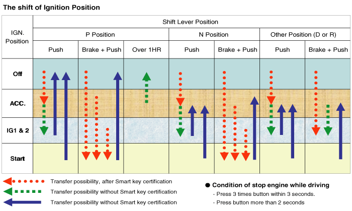
The driver can shut-off the EV by pushing the SSB button once
in a standstill position or shift position on either P or N. Emergency
engine stop can be made by long-pressing the SSB button or by
consecutively pressing 3 times in vehicle READY mode.
If the conditions for READY mode are not met while detecting a
push on the SSB or authenticating a valid fob, the system will unlock
the steering column and switch the terminals to IGN. In this case,
another push on the SSB is needed to enter READY mode.
In case of a vehicle equipped with SMART KEY system, fob
authentication will not require any action from the driver. For limp
home start or in case of vehicle without SMART KEY, the driver will have
to push the start / stop button.
| • |
Control Ignition and engine ON/OFF by Sending signal to IPM. |
| • |
Display status by LED Lamp ON/OFF. (Reddish orange or Amber) |
Indicator ON/OFF Condition At Ignition Button OFF Condition
| No. | Character lamp | Conditions |
| 1 | Indicator Lamp ON | Door open, Tail lamp ON, ACC, IG ON |
| 2 | Indicator Lamp 30sec ON > Lamp OFF | Door close, Tail lamp OFF, IG OFF |
| 3 | Indicator Lamp OFF | Remote LOCK, Passive LOCK |
| 4 | Rheostat at tail lamp ON (Illumination lamp) | |
Indicator ON/OFF Condition According To Ignition
| No. | Ignition conditions | Start Button LED status |
| 1 | IG OFF | LED OFF |
| 2 | IG ACC | Amber color LED ON |
| 3 | IG ON (Engine OFF) | Reddish orange color LED ON |
| 4 | Cranking | Maintain LED status before cranking |
| 5 | Engine running | LED OFF |
Wireless Communication
Electromagnetic waves are used to exchange information
between the vehicle and the FOB. Two types of RKE Key can supplement the
BES system:
| – |
Non-smart key RKE |
| – |
SMART KEY FOB |
Currently, all BES systems consist of SMART KEY FOB.
The transmitter, receiver and antennas required for the
communication between the fob and the vehicle will differ depending on
functionalities and regional areas.
The RKE and SMART KEY functions are in separated documents.
Refer to Smart key system for more detailed information about SMART KEY
function.
Smart Key
The SMK manages all functions related to:
| • |
"Start Stop Button (SSB) monitoring", |
| • |
"Immobilizer communication" (with Vehicle Control Unit for immobilizer release), |
| • |
"ESCL control", |
| • |
"Authentication server" (Validity of Transponder and in case of Smart Key option Passive Fob authentication ), |
| • |
"System consistency monitoring", |
| • |
"System diagnosis", |
| • |
Control of display message / warning buzzer . |
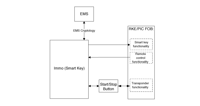
The unit behaves as Master role in the whole system.
In case of SMART KEY application, for example “Passive
Access”, “Passive Locking” and “Passive Authorization are
integrated for ESCL/Terminal switching Operations”.
It collects information about vehicle status from other
modules (e.g. vehicle speed, alarm status, driver door open, etc.),
reads the inputs (e.g. SSB, Lock Button and PARK position Switch),
controls the outputs (e.g. exterior and interior antennas), and
communicates with other devices via the CAN network as well as a single
line interfaces.
The diagnosis and learning of the components of the BES System are also handled by the SMK.
Transponder
Terminal And Starter Relays
Relays are used to switch between terminals ACC / IGN1 /
IGN2. Normally-open relays are driven by the SMK unit and are located
either in the passenger or engine compartment depending on the vehicle
architecture.
Only one relay coil is connected to the terminal outputs of the SMK unit.
These relays should integrate with a resistor connected in
parallel to the coil in order to reduce the transients during
communication.
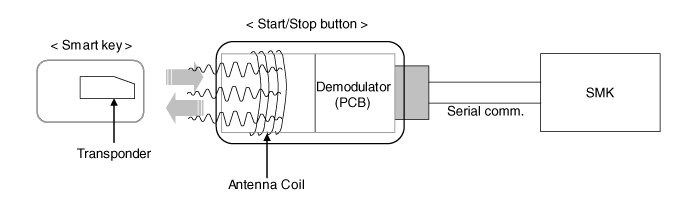
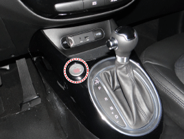
Start/Stop Button (SSB)
A single stage push button is used by the driver to operate the vehicle. By pressing this button, the driver can:
| • |
Switch between corresponding terminals to operate power modes "Off'', ''Accesory'', ''Ignition'' and ''Start'' |
| • |
Enter READY mode (standby) |
| • |
Shut-off the EV |
A backlighting is integrated to illuminate the button for the driver to easily locate the button.
Two-colored (2) LED lamps located in the center of the button
display the status of the system. Another illumination LED is also
integrated into the SSB to indicate the "Engine Start/Stop" status.
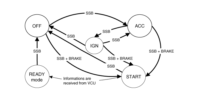
BES System State Chart
System STATES in LEARNT MODE
In learnt mode, the BES System can be set in 6 different sates, depending on the status of the terminals and Engine status:
| System State | Terminal Status | Engine status |
| 1. OFF - Locked | OFF | Stopped |
| 2. OFF - Unlocked | OFF | Stopped |
| 3. ACC | ACC | Stopped |
| 4. IGN | IGN1, IGN2, ACC | Stopped |
| 5. Start | IGN1, Start | Cranking |
| 6. IGN - Engine | IGN1, IGN2, ACC | Running (means "self-running") |
Referring to the terminals, the system states described in
the table above are the same as in a system based on a mechanical
ignition switch. One of the distinctions from Mechanical-Ignition-Switch
based system is that the BES system allows specific transition from
[OFF] to [START] without going through [ACC] and [IGN] states.
System STATES IN VIRGIN MODE
The BES System can be set in 5 different states (OFF LOCKED
is not available in virgin mode), depending on the status of the
terminals and Engine status:
| System State | Terminal Status | Engine status |
| 1. OFF - UNLOCKED | OFF | Stopped |
| 2. ACC | ACC | Stopped |
| 3. IGN | IGN1, IGN2, ACC | Stopped |
| 4. Start | IGN1, START with special pattern of activation see Chap 6.2.1 for details | Cranking |
| 5. IGN - Engine | IGN1, IGN2, ACC | Running (means "self-running") |
Referring to the terminals, the system states described in
the table above are the same as in a system based on a mechanical
ignition switch. One of the distinctions from Mechanical-Ignition-Switch
based system is that the BES system allows specific transition from
[OFF] to [START] without going through [ACC] and [IGN] states.
 Schematic Diagrams
Circuit Diagram
...
 Start/Stop Button Components and Components Location
Component
...
Other information:
Kia Soul EV (PS EV) 2015-2020 Service Manual: Pressure Source Unit Repair procedures
Removal 1. Turn ignition switch OFF and disconnect the negative (-) battery cable. 2. Disconnect the brake fluid level switch connector (A), and remove the reservoir cap. Be sure to completely remove foreign substances around brake fluid reservoir and cap be ...
Kia Soul EV (PS EV) 2015-2020 Service Manual: Rear Hub - Carrier Repair procedures
Replacement 1. Loosen the wheel nuts slightly. Raise the vehicle, and make sure it is securely supported. 2. Remove the rear wheel and tire (A) from rear hub. Tightening torque: 88.3 ~ 107.9 N.m (9.0 ~ 11.0 kgf.m, 65.1 ~ 79.6 lb-ft) 3. Loosen the guide rod bolt (B) and the remove ...
Copyright © www.ksoulev.com 2020-2025
