Kia Soul EV: AHB(Active Hydraulic Boost) System / Description and Operation
Kia Soul EV (PS EV) 2015-2020 Service Manual / Brake System / AHB(Active Hydraulic Boost) System / Description and Operation
| Description |
| Regeneration Brake System |
During deceleration or braking of an electric vehicle or HEV,
the drive motor acts as an alternator and charges the battery by
converting the vehicle’s kinetic energy generated during braking into
electrical energy.
Regenerative braking amount depends on the vehicle speed, battery SOC, etc.
Achieve significant improvement in fuel efficiency in city driving with repeated acceleration and deceleration.
| Regenerative Braking Cooperation Control (RBC) |
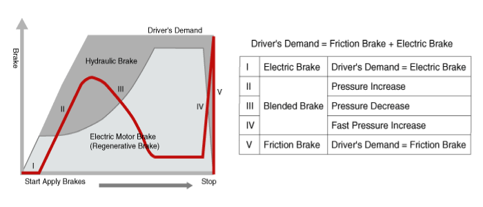
The brake force application is distributed by controlling
hydraulic braking. The total brake force output that the driver demands
is achieved by combining hydraulic and regenerative brakes. In the case
of regenerative brake failure, the total brake force that the driver
demands is supplied by the hydraulic brake system.
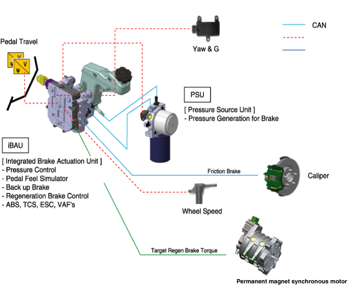
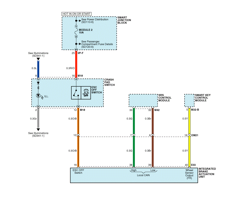
The AHB system is composed of the Pressure Source Unit (PSU) and the Integrated Brake Actuation Unit (IBAU).
First, the PSU generates the hydraulic pressure required for braking.
Similar to the boosting effect when the driver steps on the
brake pedal in a system equipped with a vacuum booster, the hydraulic
pressure stored in the cylinder is supplied to provide pressure
throughout the entire brake line.
Second, the IBAU delivers pressure generated by the PSU to a
caliper on each wheel. Also, it is connected to the brake pedal to
detect the brake force demanded by the driver and to generate the
braking feeling.
The IBAU carries out the ABS, TCS, and ESC functions as in conventional vehicles.
| AHB System Operation Principles |
| 1. Initial Status |
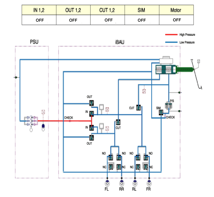
High pressure (180 bar) is generated between the PSU and the
IBAU at all times. Therefore, before removing the PSU or the IBAU, high
pressure between them should be reduced for safety by conducting"High
pressure releasemode" of GDS connected to SOUL EV.
| 2. Brake operation |
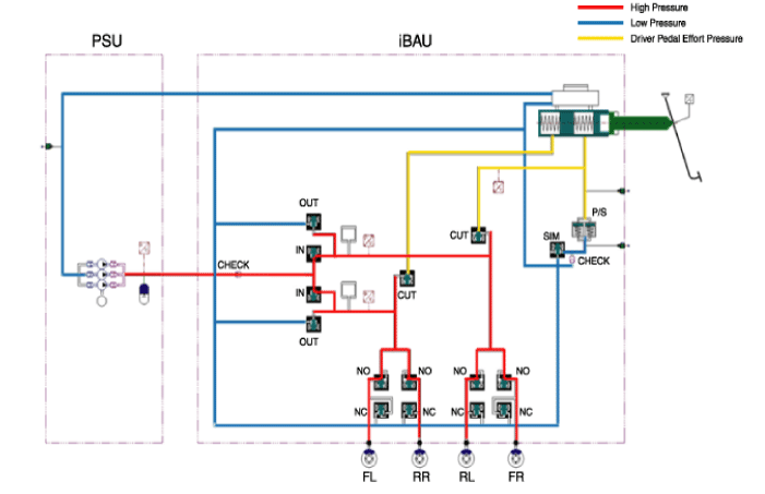
Apply Mode: When the driver presses down the brake pedal, the
IN valve turns ON, delivering the high pressure generated from PSU to
the caliper by IBAU to engage in brake operation.
The level of brake force is determined by the pedal simulator
according to the measurement of the pedal stroke sensor signal.Release
Mode: When the driver releases the brake pedal, the OUT valve opens and
the IN valve closes, returning the high pressure of brake oil back to
PSU. At the same time, the CUT valve turns ON to prevent backflow of
brake oil into the IBAU. |

| 2. Brake malfunction |
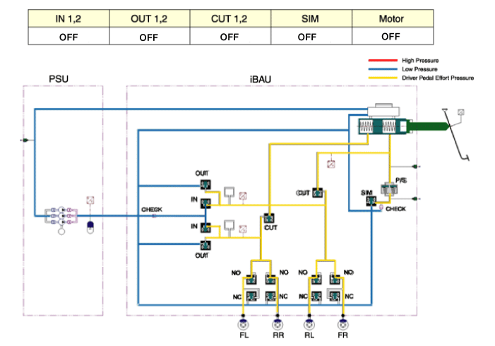
When either PSU or IBAU is faulty, both IN and OUT valves
will close and the CUT valve will turn off. In this case, brake force
can only be generated by pressing down the brake pedal manually.
| Integrated Brake Actuation Unit (IBAU) System (1) |
| Integrated Brake Actuation Unit (IBAU) System (2) |
| Integrated Brake Actuation Unit (IBAU) System (3) |
| Integrated Brake Actuation Unit (IBAU) System (4) |
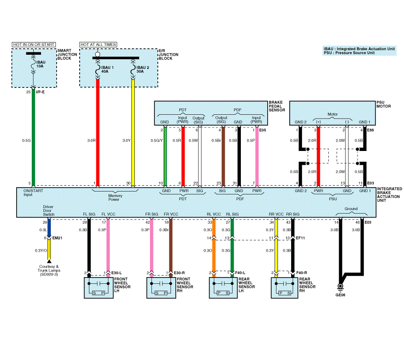
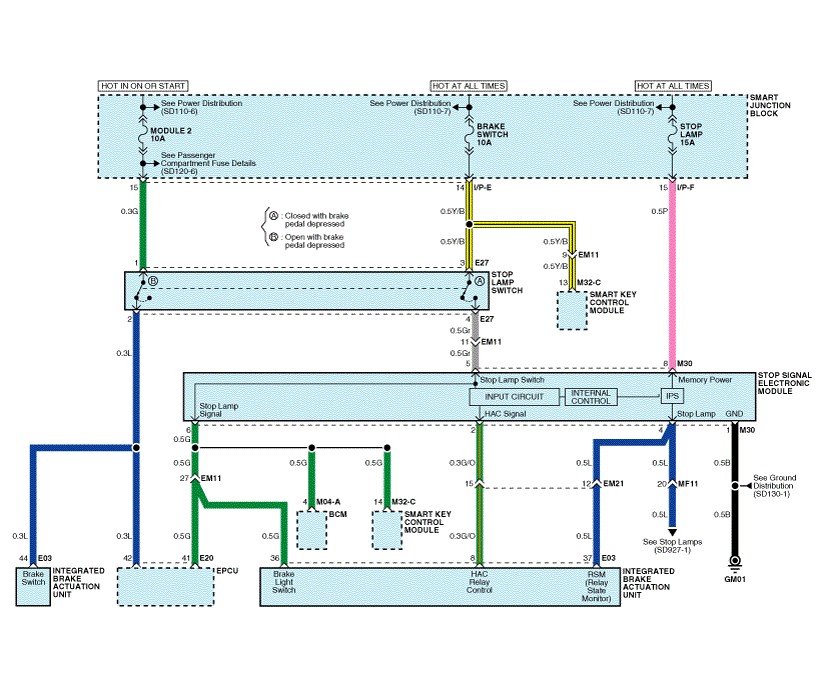
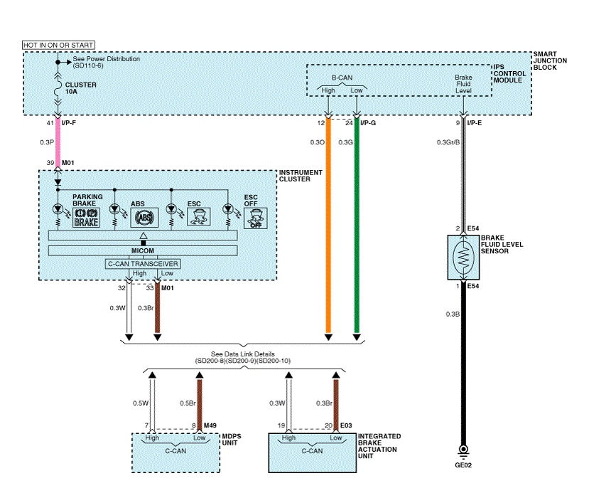
| IBAU connector input/output |
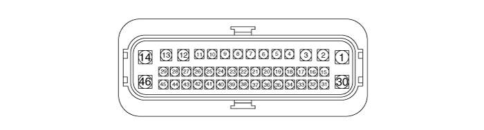
| Description | Description | ||||
| 1. | R | E/R Junction Block (Fuse - IBAU 1) | 24. | - | - |
| 2. | R | PSU Motor (+) | 25. | - | - |
| 3. | - | - | 26. | - | - |
| 4. | B | PSU Motor (Shield Ground 2) | 27. | G | Rear Wheel Sensor LH (SIG) |
| 5. | G | Smart Junction Block (Fuse - IBAU) | 28. | B | Front Wheel Sensor LH (SIG) |
| 6. | R | Brake Pedal Sensor(PDT Input (Power)) | 29. | L | Smart Junction Block(IPS Control Module) |
| 7. | P | Brake Pedal Sensor(PDF Input (Power)) | 30. | Y | E/R Junction Block (Fuse - IBAU 2) |
| 8. | G/O | Stop Signal Electronic Module(HAC Signal) | 31. | B | Brake Pedal Sensor(PDF (Ground)) |
| 9. | - | - | 32. | - | - |
| 10. | G/Y | Brake Pedal Sensor(PDT (Ground)) | 33. | O | Rear Wheel Sensor LH (VCC) |
| 11. | B | PSU Motor (Shield Ground 1) | 34. | Y | Rear Wheel Sensor RH (VCC) |
| 12. | - | - | 35. | - | - |
| 13. | W | PSU Motor (-) | 36. | G | Stop Signal Electronic Module (Stop Lamp Signal) |
| 14. | B | Ground (GE06) | 37. | L | Stop Signal Electronic Module(Stop Lamp) |
| 15. | - | - | 38. | G | SRS Control Module(Local CAN (High)) |
| 16. | O/B | Crash Pad Switch(ESC OFF Switch) | 39. | Br | SRS Control Module(Local CAN (Low)) |
| 17. | P | Front Wheel Sensor LH (VCC) | 40. | Y | Smart Key Control Module (Wheel Sensor Signal) |
| 18. | Br | Front Wheel Sensor RH (VCC) | 41. | - | - |
| 19. | W | C-CAN (High) | 42. | P | Front Wheel Sensor RH (SIG) |
| 20. | Br | C-CAN (Low) | 43. | B | Rear Wheel Sensor RH (SIG) |
| 21. | - | - | 44. | L | Stop Lamp Switch (B) |
| 22. | W | Brake Pedal Sensor(PDT Output (Signal)) | 45. | - | - |
| 23. | Br | Brake Pedal Sensor(PDF Output (Signal) | 46. | B | Ground (GE06) |
Operation and Leakage Check
Check all of the following items:
| Component | Procedure |
| Integrated Brake Actuation Unit (IBAU) (A) and Pressure Source Unit (PSU) (B) | Check
brake operation by applying the brakes during a test drive. If the
brakes do not work properly, check the IBAU and PSU. Replace IBAU and
PSU as an assembly if it does not work properly or if there are signs of
leakage. |
| Piston cup and pressure cup inspection (B) | Check
brake operation by applying the brakes. Look for damage or signs of
fluid leakage. Replace the IBAU as an assembly if the pedal does not
work properly or if there is damage or signs of fluid leakage. |
| Brake hoses (C) | Look for damage or signs of fluid leakage. Replace the brake hose with a new one if it is damaged or leaking. |
| Caliper piston seal and piston boots (D) | Check brake operation by applying the brakes. Look for damage or signs of fluid leakage. If the pedal does not work properly, the brakes drag, or there is damage or signs of fluid leakage, disassemble and inspect the brake caliper. Replace the boots and seals with new ones whenever the brake caliper is disassembled. |
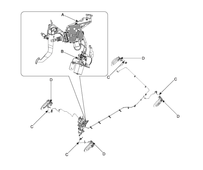

 Brake Actuation Unit Components and Components Location
Components
IBAU must not be disassembled.
1. ECU2. Reservoir3. Master cylinder Assembly4. Valve block
...
Other information:
Kia Soul EV (PS EV) 2015-2020 Service Manual: Components and Components Location
Component Location Index Engine Room [Without Heat Pump] 1. Receiver-drier2. Condensor3. A/C Pressure Transducer (APT)4. Service port (Low pressure)5. Service port (High pressure)6. Suction & Liquid tube7. Expansion valve8. Suction pipe9. Suction hose10. Electric A/C compressor [ ...
Kia Soul EV (PS EV) 2015-2020 Service Manual: Compressor Oil Repair procedures
Oil Specification 1. The HFC-134a system requires synthetic compressor oil (POE) whereas the R-12 system requires mineral compressor oil. The two oils must never be mixed. 2. Compressor oil (POE) varies according to compressor model. Be sure to use oil specified for the model of compress ...
Copyright © www.ksoulev.com 2020-2025
