Kia Soul EV: AVN System / AVN Head Unit Repair procedures

Kia Soul EV (PS EV) 2015-2020 Service Manual / Body Electrical System / AVN System / AVN Head Unit Repair procedures

Removal
   
Put on gloves to protect your hands.
   
When prying with a flat-tip screwdriver, wrap it with protective tape, and apply protective tape around the related parts, to prevent damage.
Use a plastic panel removal tool to remove interior trim pieces to protect from marring the surface.
Take care not to bend or scratch the trim and panels.
1.
Disconnect the negative (-) battery terminal.
2.
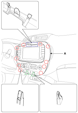
Remove the center fascia panel (A) from the crash pad.

3.
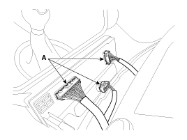
Disconnect the connectors (A) from the center fascia panel.

4.
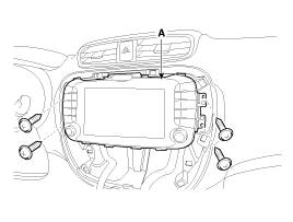
Remove the AVN head unit (A) after loosening the mounting screws.

5.
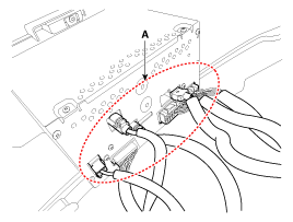
Disconnect the connectors (A) from the AVN head unit.

Installation
1.
Connect the AVN head unit connectors.
2.
Install the AVN head unit.
3.
Install the center fascia panel.
4.
Connect the negative (-) battery terminal.
   
Make sure that the AVN head unit connectors are plugged in properly and the antenna cable is connected properly.
Inspection
1.
Check the specified value of AVN head unit connectors in specified condition.
Connector A
No.
Name
Terminal Description
Condition
Specified Condition
A1
Rear left speaker (+)
Loudspeaker Rear Left+
Needs connection to the car
Analog output
A2
Front left speaker (+)
Loudspeaker Front Left+
Needs connection to the car
Analog output
A3
Front right speaker (+)
Loudspeaker Front Right+
Needs connection to the car
Analog output
A4
Rear right speaker (+)
Loudspeaker Rear Right+
Needs connection to the car
Analog output
A5
-
-
?
?
A6
-
-
?
?
A7
-
-
?
?
A8
Illumination (+)
Rheostat from vehicle +
Needs connection to the car
?
A9
Detent
Detent
Needs connection to the car
?
A10
Rear left speaker (-)
Loudspeaker Rear Left-
Needs connection to the car
Analog output
A11
Front left speaker (-)
Loudspeaker Front Left-
Needs connection to the car
Analog output
A12
Front right speaker (-)
Loudspeaker Front Right-
Needs connection to the car
Analog output
A13
Rear right speaker (-)
Loudspeaker Rear Right-
Needs connection to the car
Analog output
A14
-
-
?
?
A15
-
-
?
?
A16
-
-
?
?
A17
Illumination (-)
Rheostat from vehicle -
Needs connection to the car
?
A18
Remote antenna
Remote Power supply for Antenna
Acc on
9V ~ 18V

Connector B
No.
Name
Terminal Description
Condition
Specified Condition
B1
MM CAN high
MM_CAN_HIGH
Needs connection to the car
Communication with external amp
B2
-
-
-
-
B3
Parking
PARKING from vehicle 
-
-
B4
Steering remocon
Steering Wheel Remote Control
Steering Wheel switch pushed
0.5V ~ 3V
B5
-
-
-
-
B6
MTS key
-
-
-
B7
AUX video
AUX Video
Needs connection to the MultiJack
-
B8
AUX right input
AUX Right Sound Signal
External Auxiliary device is Audio playing
(At time of Aux jack use)
A waveform synchronized with sound is output
B9
AUX ground
AUX Reference Ground
Needs connection to the MultiJack
Below 1 ohm
B10
MIC (+)
Bluetooth MIC+
Input the Voice Signal via MIC
A waveform synchronized with Voice data via MIC
B11
Battery (+)
Battery
Always
11 ~ 14 V
B12
Battery (+)
Battery
Always
11 ~ 14 V
B13
MM CAN low
MM_CAN_LOW
Needs connection to the car
Communication with external amp
B14
Auto light
AUTO-LIGHT from vehicle 
-
-
B15
P position
P-POSITON from vehicle 
-
-
B16
Speed
Speed Sensor Signal
Engine switch on(IGN), car is moved slowly
Approx. 5V Level Pulse Generation
B17
Remocon ground
Steering Wheel Remote Control GND
Always
Below 1 ohm
B18
ACC
Accessory
Engine switch on(ACC)
11 ~ 14 V
B19
AUX video ground
AUX Video GND
Always
Below 1 ohm
B20
AUX DETECT
AUX Signal Input Detect
Auxiliary device is inserted
0V(Low) > 5V(High)
B21
AUX left input
AUX Left Sound Signal
External Auxiliary device is Audio playing
(At time of Aux jack use)
A waveform synchronized with sound is output
B22
MIC (-)
Bluetooth MIC-
Input the Voice Signal via MIC
A waveform synchronized with Voice data via MIC
B23
Ground
Ground
Always
Below 1 ohm
B24
Ground
Ground
Always
Below 1 ohm

Connector C
No.
Name
Terminal Description
Condition
Specified Condition
C1
C CAN (-)
CHASSIS_CAN_LOW
Needs connection to the car
-
C2
C CAN (+)
CHASSIS_CAN_HIGH
Needs connection to the car
-
C3
-
-
-
-
C4
-
-
-
-
C5
OBC wake up
-
-
-
C6
-
-
-
-
C7
-
-
-
-
C8
-
-
-
-
C9
-
-
-
-
C10
-
-
-
-
C11
B CAN (+)
BODY_CAN_HIGH
Needs connection to the car
-
C12
B CAN (-)
BODY_CAN_LOW
Needs connection to the car
-
C13
-
-
-
-
C14
Airbag
AIRBAG from vehicle 
-
-
C15
-
-
AVN Head Unit Components and Components Location
Components AVN (A/V & Navigation) Head Unit Connector Connector Pin Information No.Connector AConnector BConnector C1Rear left speaker (+)MM CAN highC CAN (-)2Front left speaker (+)-C CAN ...

Speaker Repair procedures
Inspection 1. Troubleshooting for Speaker (1) Basic inspection of speaker Inspect the sound from speaker after verifying that the speaker mounting screws are removed and the wiring connector ...

Other information:

Kia Soul EV (PS EV) 2015-2020 Service Manual: Front Bumper Cover Components and Components Location


Component Location 1. Front bumper cover ...

Kia Soul EV (PS EV) 2015-2020 Service Manual: Intake Actuator Repair procedures


Inspection 1. Turn the ignition switch OFF. 2. Disconnect the intake actuator connector. 3. Verify that the actuator operates to the recirculation position when 12V is connected to terminal 3 and ground to terminal 7. Verify that the intake actuator operates to the recirculated air posi ...

Copyright © www.ksoulev.com 2020-2024