Kia Soul EV: Tires/Wheels / Tire Repair procedures
Kia Soul EV (PS EV) 2015-2020 Service Manual / Suspension System / Tires/Wheels / Tire Repair procedures
| Tire Wear |
| 1. |
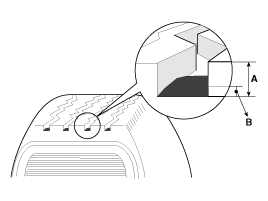
Measure the tread depth of the tires.
|
| 2. |
If the remaining tread depth (A) is less than the limit, replace the tire.
|
Tire Rotation
| Checking For Pull And Wander |
|
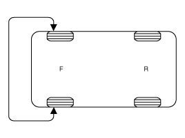
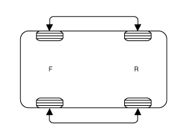
If the steering pulls to one side, rotate the tires according to the following wheel rotation procedure.
| 1. |
Rotate the front right and front left tires, and perform a road test in order to confirm vehicle stability.
|
| 2. |
If the steering pulls to the opposite side, rotate the front and rear tires, and perform a road test again.
|
| 3. |
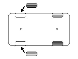
If the steering continues to pull to one side, rotate the front right and left tires again, and perform a road test.
|
| 4. |
If the steering continues to pull to the opposite side, replace the front wheels with new ones.
|
| Removal |
|
| 1. |
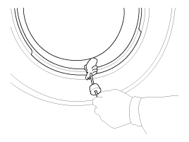
Remove valve core and deflate the tire. |
| 2. |
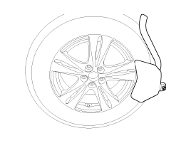
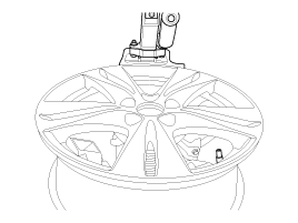
Remove the side of the tire bead area from the wheel using tire changing machine .
|
| 3. |
Rotate the wheel clockwise.
|
| Installation |
| 1. |
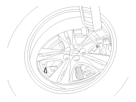
Apply tire soap or lubrication to the top and bottom tire beads.
|
| 2. |
To fit the bottom bead, position the valve at the 5 o’clock position relative to the head on the tire changing machine.
|
| 3. |
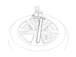
Place the tire on the rim so the bottom bead touches the
edge of the rim after the valve (6 o’clock). Rotate the rim clockwise,
and push down on the tire at the 3 o’clock position to fit bottom
bead.
|
| 4. |
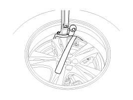
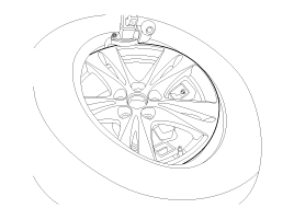
After bottom bead is on tire, rotate the rim until the valve
is at the 5 o’clock position relative to the head on the tire changing
machine. Push down on the tire at the 3 o’clock position and rotate
the rim clockwise to fit the top bead.
|
| 5. |
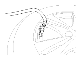
Inflate the tire until both beads seat.
|
 Tires/Wheels
...
 Wheel Repair procedures
Hub nut tightening sequence
Tighten the hub nuts as follows.
Tightening torque:
88.3 ~ 107.9N.m (9.0 ~ 11.0kgf.m, 65.1 ~ 79.6lb-ft)
When using an impact gun, fin ...
Other information:
Kia Soul EV (PS EV) 2015-2020 Service Manual: Main Crash Pad Assembly Repair procedures
Replacement • Put on gloves to protect your hands. • When prying with a flat-tip screwdriver, wrap it with protective tape, and apply protective tape around the related parts, to prevent damage. • Us ...
Kia Soul EV (PS EV) 2015-2020 Service Manual: Seat Belt Pretensioner (BPT) Description and Operation
Description The Seat Belt Pretensioners (BPT) are installed inside Center Pillar (LH & RH). When a vehicle crashes with a certain degree of frontal impact, the pretensioner seat belt helps to reduce the severity of injury to the front seat occupants by retracting the seat belt webbing ...
Copyright © www.ksoulev.com 2020-2025


